The global laser cutting machine market was valued at $7.43 billion in 2024, projected to reach $10.35 billion by 2030 at a 5.7% annual growth rate. That kind of momentum reflects genuine adoption, not hype.
Yet for all their prevalence, the internal mechanics remain surprisingly opaque to many buyers, fabricators, and shop owners evaluating the technology. Understanding how the machine actually works — from how the beam gets generated to how assist gas determines edge quality — directly affects purchasing decisions, parameter settings, and the ability to troubleshoot cut quality problems.
This guide walks through the complete process, stage by stage.
Key Takeaways
- Fiber lasers emit light near 1.06 microns through ytterbium-doped optical fiber, a wavelength metals absorb far more efficiently than CO2 laser light
- Cutting runs through four distinct stages — laser generation, beam delivery, material interaction, and CNC motion control — each affecting the final result
- Assist gas (oxygen, nitrogen, or compressed air) is not optional — it determines edge quality and cut efficiency
- Power ratings from 1kW to 40kW+ dictate which materials and thicknesses are achievable
- For shops prioritizing cost-effectiveness on thicker carbon steel, CNC plasma cutting remains a practical alternative worth evaluating
What Is a Fiber Laser Cutting Machine?
A fiber laser cutting machine is a CNC machine tool that uses a high-density laser beam — generated through an ytterbium-doped optical fiber — to melt or vaporize metal along digitally programmed paths. The result: precise, clean cuts with no physical tool contact.
The technology emerged to address real limitations in earlier cutting methods. CO2 lasers required complex mirror systems and struggled on reflective metals. Mechanical cutting introduced tool wear and couldn't match the geometric complexity achievable digitally. Fiber lasers solved both problems.
How Fiber Lasers Compare to Other Cutting Methods
Three technologies are commonly compared in metal cutting: CO2 lasers, plasma cutters, and waterjets. CO2 systems use gas discharge tubes and mirror-based beam delivery at 10.6 microns. Plasma cutters run an ionized gas arc to conduct electrical current through the material. Waterjets mix high-pressure water with abrasive particles to erode the cut path.
Each has its place. Fiber lasers dominate sheet metal and precision cutting environments because of several measurable advantages:
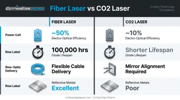
- High electro-optical efficiency — high-power fiber lasers can reach around 50% wall-plug efficiency, compared to roughly 10% for CO2 lasers
- Long diode lifespan — laser diode lifetimes can extend into the 100,000-hour range
- Flexible beam delivery — the beam travels via fiber optic cable, eliminating the mirror systems CO2 lasers require
- Superior reflective metal performance — metals absorb the ~1-micron wavelength far more effectively than the 10.6-micron CO2 wavelength
Power Classifications
| Power Range | Typical Application |
|---|---|
| Under 500W | Marking and engraving |
| 500W – 3kW | Thin sheet cutting |
| 3kW – 20kW+ | Medium to thick plate cutting |
Machines also run in either continuous wave (CW) or pulsed wave mode, a distinction that affects which materials and surface finishes are achievable.
Key Components of a Fiber Laser Cutting System
A fiber laser cutting machine is a coordinated system of interdependent components — each one plays a specific role in turning electrical power into a precise cut.
Core Components
- Fiber laser source — generates and amplifies the beam using rare-earth doped optical fiber
- Cutting head — houses the collimating and focusing lenses plus the nozzle
- CNC controller — interprets design files, directs axis movement, and manages beam parameters in real time
- Assist gas system — delivers oxygen, nitrogen, or compressed air coaxially through the nozzle at the cut zone
- Cooling system/water chiller — manages residual heat generated during photoelectric conversion
The Motion System
The machine operates on X, Y, and Z axes driven by servo motors. The cutting head traces any 2D path (or 3D path on more advanced systems) across the workpiece. Positioning accuracy on industrial systems can reach 0.05mm per 500mm of travel, with repeatability of approximately ±0.01mm — though these figures are model-specific and shouldn't be generalized across all machines.
The laser source and the cutting point are not the same unit — a distinction worth understanding before you buy. The laser generator produces the beam, but it doesn't emit it directly at the material. The beam travels via fiber optic cable to the cutting head, where it contacts the workpiece. CO2 lasers, by contrast, route the beam through a series of precisely aligned mirrors — an arrangement that introduces more alignment-related maintenance and potential failure points.
How Does a Fiber Laser Cutting Machine Work?
Fiber laser cutting runs through a defined sequence of stages. Each one affects the precision, speed, and edge quality of the final cut.
Stage 1: Laser Generation
The process starts with pump diodes — typically operating around 976nm — that generate seed light fed into optical fiber doped with ytterbium ions. The pump light energizes those ions, exciting electrons to higher energy states. When they relax, they release amplified photons through stimulated emission.
The result: a coherent, high-intensity laser beam.
The resulting emission wavelength sits near 1,070nm (approximately 1.06 microns). That wavelength is the key to fiber laser performance on metal: common fabrication metals absorb more and reflect less of 1-micron wavelength light than they do 10.6-micron CO2 light. This is why fiber lasers cut copper, brass, and aluminum reliably — materials that reflect CO2 beams back toward the optics and create serious reliability problems.
Once initiated, this is an automated, continuous process. The operator doesn't manually trigger each emission. The CNC system coordinates beam timing with axis movement.
Stage 2: Beam Delivery and Focusing
The amplified beam travels from the laser source through a flexible fiber optic cable directly to the cutting head. There are no mirrors, no alignment drift, and no bellows to maintain. Inside the cutting head, two lenses do the critical work:
- Collimating lens: takes the diverging beam exiting the fiber and parallelizes it
- Focusing lens: concentrates it into a micro-spot at the focal point
Focal spot sizes on material typically range from around 100 microns up to more than 1mm, depending on the lens configuration and laser mode. At that concentration, the power density is sufficient to exceed the melting or vaporization threshold of the target metal almost instantly.
Focal position matters significantly. Depending on material type and thickness, the focal point is set at the surface, mid-depth through the material, or slightly below the surface. Focal diameter directly determines kerf width, while focal position affects the kerf shape and edge consistency. Improper focal adjustment produces rough edges, incomplete cuts through thick material, or excessive heat-affected zones — all diagnosable problems once you understand the cause.
Stage 3: Material Interaction and Assist Gas
When the focused beam contacts the workpiece, it transfers intense localized energy. The metal melts or vaporizes within the beam's footprint. No physical tooling touches the material — no tool wear, no mechanical stress on the workpiece.
Simultaneously, assist gas is delivered through the nozzle, centered on the beam. The gas choice shapes the cut result:
| Gas | Function | Best For |
|---|---|---|
| Oxygen | Creates an exothermic reaction that accelerates cutting; leaves oxidized edge | Mild steel, high-speed production |
| Nitrogen | Inert; prevents oxidation for a clean, bright edge | Stainless steel, aluminum |
| Compressed air | Cost-effective; ~78% nitrogen, ~21% oxygen | Thin materials, lower-priority edge quality |
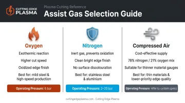
Oxygen flame cutting uses pressures up to approximately 6 bar. Nitrogen fusion cutting typically operates between 2 and 20 bar. Cutting without any assist gas produces poor edge quality and risks damaging the optics — it's not a viable shortcut.
Stage 4: CNC Motion and Cut Control
With material interaction and gas delivery handled, the CNC controller ties it all together. It reads the design file — typically converted from CAD into G-code or a machine-specific format — and simultaneously manages:
- Cutting head position across X, Y, and Z axes
- Laser power output
- Cutting speed
- Gas type and pressure
These parameters must be matched to the specific material and thickness. Cut too fast, and the beam doesn't fully penetrate. Cut too slow, and excess heat causes warping, dross buildup on the cut edge, or burn-through on thin material.
The practical advantage of CNC automation: once the correct parameters are dialed in for a given material and thickness, they can be saved and recalled for every subsequent production run — delivering repeatable results without operator-by-operator variation.
Where Fiber Laser Cutting Machines Are Used
Fiber laser cutting fits primarily into sheet metal fabrication workflows — cutting flat plate before forming, welding, or finishing — and precision parts manufacturing where tight tolerances and complex geometries are required.
Industries that rely on fiber laser cutting:
- Automotive — body panels, brackets, exhaust components
- Aerospace — lightweight alloy structures requiring tight dimensional control
- Electronics — enclosures, heat sinks, chassis components
- HVAC and ductwork — sheet metal components in high volume
- Metal art and decorative fabrication — intricate cuts in stainless and aluminum
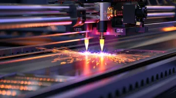
The technology scales from high-volume industrial production lines running 20kW+ systems to smaller custom shops with 3kW or 6kW machines handling mixed job work. That range matters, because the right machine depends heavily on your production volume and budget.
A Practical Note for Smaller Shops
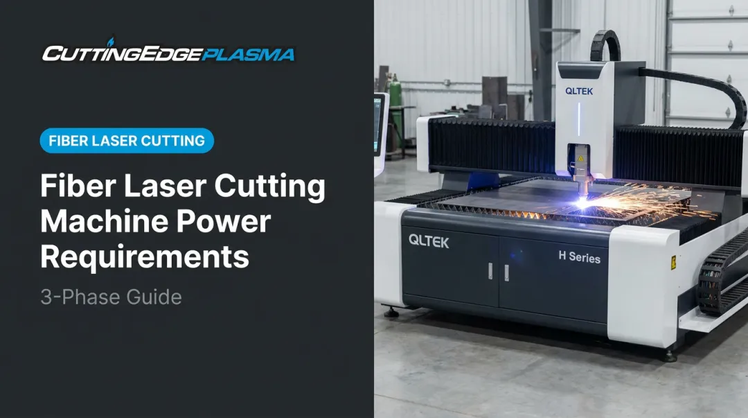
Fiber laser cutting is exceptional at what it does — but it's optimized for metal, requires significant capital investment (starting around $54,000 for entry-level systems like the QLTEK H Series), and demands controlled operating conditions.
For hobbyists, small business owners, and fabricators who need cost-effective metal cutting across a range of thicknesses, CNC plasma cutting tables are worth a hard look. They handle thicker carbon steel well and cost far less upfront. Cutting Edge Plasma's iPlasma XTREME series starts at $17,495, pairs with Hypertherm Powermax plasma cutters up to 125 amps, and can cut carbon steel up to 32mm at production speeds. For shops that aren't running high-precision thin-sheet work daily, plasma gets the job done without the fiber laser price tag.
Frequently Asked Questions
How does a fiber laser cutting machine work?
A fiber laser cutting machine generates a high-intensity beam through ytterbium-doped optical fiber, focuses it onto the material using precision lenses in the cutting head, and uses CNC-guided movement plus assist gas to melt or vaporize the metal along a programmed path. These four stages — generation, beam delivery, material interaction, and motion control — run in coordinated sequence to produce each cut.
How thick can a 1kW fiber laser cut?
A 1kW fiber laser cuts approximately 10mm of carbon steel, around 5mm of stainless steel, and roughly 3mm of aluminum under typical conditions. Treat these as directional figures: actual results shift based on assist gas, cutting speed, edge quality requirements, and machine configuration.
Do fiber lasers require gas?
Yes: assist gas is a functional requirement, not an option. It clears molten material from the kerf, prevents oxidation (nitrogen), or accelerates the cutting reaction (oxygen). Cutting without assist gas produces poor edge quality and risks damaging the cutting head optics.
What materials can a fiber laser cutting machine cut?
Fiber lasers perform best on metals: mild steel, stainless steel, aluminum, copper, brass, and titanium. They can process some non-metals, but are unsuitable for materials like PVC or polycarbonate that release toxic gases when laser-heated.
How does fiber laser cutting compare to plasma cutting?
Fiber laser cutting delivers higher precision and better edge quality, especially on material under 6mm. Plasma cutting handles thicker plate more cost-effectively, requires less capital investment, and is generally faster on carbon steel above 16mm — making it a practical choice for many fabricators working with heavier stock.